What are Free Body Diagrams?
A free body diagram (FBD) is a simplified visual representation of an object and the forces acting upon it. It’s an essential tool in physics for analyzing forces and solving problems related to motion, equilibrium, and dynamics. In a free body diagram, we isolate the object (hence “free body”) and draw arrows representing all the forces applied to it. Each force arrow has a direction and a magnitude, giving a clear picture of the interactions that influence the object’s motion.
Table of Contents
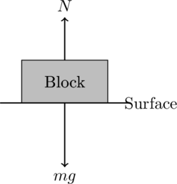
Sample Free body diagram:
- The block is represented by a rectangle.
- The two forces acting on the block are the gravitational force mgmgmg (downward) and the normal force NNN (upward).
- The surface on which the block rests is shown as a horizontal line.
How to Draw Free Body Diagrams
- Identify the object: Choose the object that you want to analyze and represent it as a simple point or box.
- Isolate the object: Imagine removing the object from its surroundings so that you can focus solely on it and the forces acting upon it.
- Draw the forces: For each interaction between the object and the environment, draw an arrow representing the force. The direction of the arrow shows the direction of the force, and the length of the arrow indicates the relative magnitude of the force.
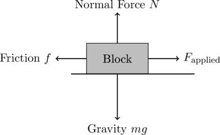
- Gravity: Always acts downward, toward the center of the Earth.
- Normal Force: A support force exerted by a surface that is perpendicular to the surface.
- Tension: A force transmitted through a string, rope, or cable.
- Friction: ACTs parallel to the surface, opposing the motion or the tendency of motion.
- Applied Force: Any other force directly exerted on the object (like a push or pull).
- Label the forces: Clearly label each force, typically with symbols like
for gravitational force,
for normal force, and
for frictional force.
- Check for equilibrium or acceleration: Based on Newton’s laws of motion, determine whether the forces balance out (indicating equilibrium) or whether there is a net force, causing acceleration.
Examples of Free Body Diagrams in High School Physics
Free Body Diagram Example 1: Block on a Horizontal Surface
Scenario: A block is resting on a flat, frictionless surface.
Forces ACTing on the Block:
- Gravitational Force (
): ACTs downward.
- Normal Force (
): ACTs upward, perpendicular to the surface.
Free Body Diagram:
Explanation:
- The gravitational force (
) pulls the block downward.
- The normal force (
) pushes the block upward.
- Since the surface is frictionless and there are no other vertical forces,
, indicating the block is in equilibrium vertically.
Free Body Diagram Example 2: Block on an Inclined Plane
Scenario: A block slides down a 30° inclined plane with friction.
Forces ACTing on the Block:
- Gravitational Force (
): ACTs vertically downward.
- Normal Force (
): Perpendicular to the inclined surface.
- Frictional Force (
): Opposes the motion, parallel to the surface.
Free Body Diagram:
Explanation:
- The gravitational force (
) pulls the block downward.
- The normal force (
) is perpendicular to the inclined plane.
- The frictional force (
) opposes the motion of the block, acting parallel to the surface.
To find the net force and acceleration, you would decompose the gravitational force into two components:
- Parallel to the plane:
.
- Perpendicular to the plane:
.
The frictional force is given by , where
is the coefficient of friction.
Free Body Diagram Example 3: Car Braking on a Flat Surface
Scenario: A 1200 kg car is moving at 20 m/s and brakes are applied, generating a frictional force of 6000 N.
Forces ACTing on the Car:
- Gravitational Force (
): ACTs downward.
- Normal Force (
): ACTs upward.
- Frictional Force (
): ACTs opposite to the direction of motion.
Free Body Diagram:
Explanation:
- The gravitational force (
) pulls the car downward, while the normal force (
) balances it.
- The frictional force (
) opposes the car’s motion.
The deceleration is found using Newton’s second law:
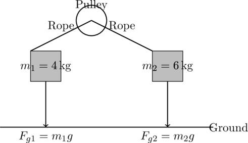
Example 4: Hanging Masses Connected by a Pulley
Scenario: Two masses are connected by a rope over a pulley: and
.
Forces ACTing on Each Mass:
- Mass 1: Tension (
) upward, weight (
) downward.
- Mass 2: Tension (
) upward, weight (
) downward.
Free Body Diagram:
Explanation:
- For each mass, tension
opposes the gravitational force.
- The system accelerates based on the difference in the gravitational forces on the two masses.
Free Body Diagrams Practical Applications
Free body diagrams are widely used in physics and engineering to analyze forces acting on an object in various scenarios. They help in simplifying complex problems by representing all forces in a clear, visual format. Here are examples of where one might use free body diagrams. Let’s address each of these categories with a detailed question and solution, including a Free Body Diagram (FBD) for each scenario. I’ll provide practical, realistic applications for each and represent them visually using LaTeX.
1. Free Body Diagrams in Mechanical Engineering (Statics)
In mechanical engineering, free body diagrams are crucial for analyzing structures and machines. For example, when designing a bridge, engineers use free body diagrams to determine the forces acting on each segment and to ensure the structure can handle the weight and external forces like wind and traffic.
Question:
An engineer is analyzing a beam supported at two ends (A and B) that is subjected to a uniform load of over a span of
. Calculate the reaction forces at supports A and B. Assume the beam is in static equilibrium.
Step-by-Step Solution:
- Identify forces acting on the beam:
- The uniform load creates a downward force over the length of the beam.
- The reactions at points A and B (denoted
and
) act upward.
- Free Body Diagram:
The total downward force is the product of the load per meter and the total length of the beam: - Static equilibrium conditions:
- Sum of vertical forces = 0:
- Taking moments about point A:
Substituting:
- From
, we find:
Final Answer:
The reaction forces at A and B are both 1500 N upward.
FBD:
2. Free Body Diagrams in Automotive Engineering
Free body diagrams are used to analyze the dynamics of a vehicle, such as cornering a car on a banked road. These diagrams help engineers understand the forces involved, such as friction, gravity, and normal force, to ensure stability and safety.
Question:
A car is driving on a banked curve of radius with a banking angle of
. If the car moves without relying on friction, determine the speed at which the car should travel for the centripetal force to be provided solely by the normal force.
Step-by-Step Solution:
- Identify forces acting on the car:
- Gravitational force:
acting vertically downward.
- Normal force: ( N ) acting perpendicular to the surface of the banked road.
- The horizontal component of the normal force provides the centripetal force required to keep the car moving in a circle.
- Free Body Diagram:
- The vertical and horizontal components of the normal force must balance gravity and provide the centripetal force, respectively.
- Equilibrium in the vertical direction:
- Centripetal force requirement:
- Solving for velocity:
Dividing the two equations:
Substituting:
Final Answer:
The car should travel at a speed of 16.8 m/s to rely only on the normal force for the centripetal force.
FBD:
3. Free Body Diagrams in Physics Education (Newton’s Laws)
In introductory physics classes, students often use free body diagrams to solve problems related to Newton’s laws of motion, such as a block on an inclined plane or an object in free fall. These diagrams help in calculating acceleration, net force, and tension.
Question:
A block of mass is placed on an inclined plane making an angle of
with the horizontal. Calculate the acceleration of the block assuming no friction.
Step-by-Step Solution:
- Identify forces acting on the block:
- Gravitational force ( mg ) acting downward.
- Normal force ( N ) acting perpendicular to the surface.
- The component of gravitational force parallel to the incline causes the block to accelerate.
- Free Body Diagram:
- The forces are broken down into components parallel and perpendicular to the inclined plane.
- Equations of motion:
- The force parallel to the incline is
.
- The normal force is
.
- Applying Newton’s second law along the incline:
Substituting:
Final Answer:
The block accelerates down the plane at ( 4.9 \, \text{m/s}^2 ).
FBD:
4. Free Body Diagrams in Robotics and Aerospace (Rocket Launch)
Free body diagrams are essential in designing robotic arms and spacecraft. For example, in aerospace, they help analyze the forces acting on a rocket during launch, such as thrust, drag, and gravitational forces.
Question:
A rocket of mass is launched vertically. The engines exert a constant thrust of
. Determine the acceleration of the rocket at launch (ignore air resistance).
Step-by-Step Solution:
- Identify forces acting on the rocket:
- Thrust force
acting upward.
- Gravitational force
acting downward.
- Free Body Diagram:
- The net force on the rocket is the difference between the thrust and gravitational forces.
- Newton’s second law:
Solving for acceleration ( a ):
Substituting the values:
Final Answer:
The acceleration of the rocket is 14.2 m/s² upward.
FBD:
5. Free Body Diagrams in Biomechanics (Human Motion)
In biomechanics, free body diagrams are used to study human movements. For instance, they are used to analyze the forces on a person’s leg while running or the forces on joints during exercise to prevent injuries or optimize performance.
These are just a few examples, and free body diagrams can be applied in any scenario involving forces, motion, or equilibrium.
Question:
A runner pushes off the ground with a force of at an angle of
to the horizontal. Determine the horizontal and vertical components of this force.
Step-by-Step Solution:
- Identify the force acting on the runner:
can be broken down into horizontal and vertical components using trigonometry.
- Free Body Diagram:
- The horizontal component is
.
- The vertical component is
.
- Calculations:
- Horizontal component:
- Vertical component:
Final Answer:
The horizontal component is 566 N and the vertical component is 566 N.
FBD:
Each question and diagram illustrates how free body diagrams can simplify complex force interactions and help find solutions in various fields.
More practice Free Body Diagrams Physics Questions (with Answers)
Here are 10 advanced physics questions that require the use of free body diagrams, categorized by test type, starting from easier questions and progressing to more difficult ones. The questions involve different variables and a variety of objects and contexts.
MCAT Free Body Diagram Physics: Question 1
Object on an Inclined Plane
A 5 kg block is placed on a frictionless inclined plane that makes an angle of 30° with the horizontal. What is the acceleration of the block as it slides down the plane?
Step-by-Step Solution:
- Draw the free body diagram to show the object on an inclined plane: The forces acting on the block include:
- The gravitational force ( F_g = mg ), which acts vertically downward.
- The normal force ( N ), which is perpendicular to the surface of the inclined plane.
- Since the surface is frictionless, no frictional force acts along the incline.
- Decompose the gravitational force: The gravitational force ( F_g = mg ) can be split into two components:
- A component parallel to the plane:
.
- A component perpendicular to the plane:
.
- Apply Newton’s second law along the incline: Since there is no friction and the only force causing acceleration is the parallel component of gravity:
Thus:
The mass cancels out:
Substitute the values:
- ( g = 9.8 \, \text{m/s}^2 )
- ( \theta = 30^\circ ) So:
Final Answer:
The acceleration of the block down the plane is .
12th Grade Free Body Diagram Physics Question 2
Tension in a Rope
A 10 kg object is suspended by two ropes forming an angle of 60° with the horizontal. What is the tension in each rope?
Answer to 12th Grade Physics: Question 2
Tension in a Rope
A 10 kg object is suspended by two ropes forming an angle of 60° with the horizontal. What is the tension in each rope?
Step-by-Step Solution:
- Draw the free body diagram to show tension in the rope: The object is in equilibrium, so the net force is zero. The forces acting on the object are:
- The gravitational force ( F_g = mg ) acting downward.
- Two tension forces ( T ), acting upward and at an angle ( \theta = 60^\circ ) to the horizontal.
- Apply equilibrium conditions: Since the object is in equilibrium, the forces in both the horizontal and vertical directions must balance out. Vertical direction:
The vertical components of the tension forces must balance the weight of the object:
Horizontal direction:
The horizontal components of the tension forces cancel each other out:
Solve for tension:
In the vertical direction:
Substituting the known values:
Simplifying:
Therefore:
.
Final Answer:
The tension in each rope is approximately .
MCAT Free Body Diagram Physics Question 3
Forces on a Pulley System
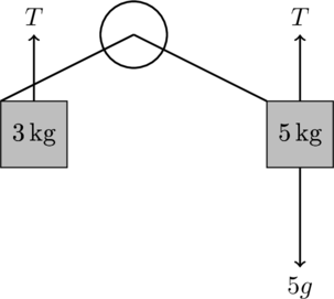
A 3 kg block is connected by a string over a frictionless pulley to a 5 kg block hanging vertically. Draw the free body diagram for each block and calculate the acceleration of the system.
Step-by-Step Solution:
- Draw the free body diagram for each block to show forces on a pulley system:
- For the 3 kg block on the table, the forces are the tension ( T ) in the rope and its weight ( F_g = 3g ), but there is no vertical motion.
- For the 5 kg hanging block, the forces are the tension ( T ) and the gravitational force ( F_g = 5g ).
- Write the equations of motion for both blocks:
- For the 3 kg block (on the table):
For the 5 kg block (hanging):
- Solve the system of equations: Add the two equations:
Rearranging:
Substituting ( g = 9.8 \, \text{m/s}^2 ):
Solving for ( a ):
Final Answer:
The acceleration of the system is
12th Grade Free Body Diagram Physics Question 4
Frictional Force on a Horizontal Surface
A ball is thrown horizontally from a height of 20 m with a velocity of 15 m/s. How far from the base of the cliff will the ball land?
Step-by-Step Solution:
- Draw the free body diagram of the frictional force acting on a horizontal surface: The ball is projected horizontally, meaning its initial vertical velocity is zero. The horizontal velocity remains constant throughout the motion, while the vertical velocity increases due to gravity. We can split the motion into two components:
- Horizontal motion: Constant velocity.
- Vertical motion: Accelerated motion due to gravity.
- Determine the time to fall: The vertical motion is governed by the equation:
Since the initial vertical velocity, the equation simplifies to:
Substitutingand
):
Simplifying:
Solving for ( t ): - Determine the horizontal distance traveled: In horizontal motion, the velocity remains constant at
, and the horizontal distance ( x ) is given by:
Substitutingand
:
Final Answer:
The ball will land approximately 30.3 meters from the base of the cliff.
G12 Conceptual Free Body Diagram Physics Question 5
Centripital Forces
A car of mass 1000 kg is traveling at a speed of 20 m/s around a circular track of radius 50 m. What is the magnitude of the centripetal force acting on the car?
Step-by-Step Solution:
- Draw the free body diagram of the centripital force: The car is moving in a circle, so it experiences a centripetal force that points towards the center of the circular path. The only force contributing to this centripetal acceleration is friction between the tires and the road (assuming no banking of the road).
Use the formula for centripetal force:
The centripetal force is given by:
Where:
is the mass of the car.
is the speed of the car.
is the radius of the circular track.
- Substitute the values:
Simplifying:
Final Answer:
The magnitude of the centripetal force acting on the car is 8000 N.
MCAT Free Body Diagram Physics Question 6
Work Done by a Force
A 50 N force is applied at an angle of 30° to the horizontal to pull a box 10 m along a frictionless surface. How much work is done by the force?
Step-by-Step Solution:
- Draw the free body diagram of the work done by force: The force
is applied at an angle
to the horizontal. Only the horizontal component of the force contributes to the work done on the box.
Calculate the horizontal component of the force:
The horizontal component of the force is:
Substituting and
:
Calculate the work done:
Work is given by the equation:
Where:
is the horizontal component of the force.
is the distance moved by the box. Substituting the values:
Final Answer:
The work done by the force is 433 J.
12th Grade Free Body Diagram Physics Question 7
Inclined Plane
A block of mass 5 kg is placed on a frictionless inclined plane that makes an angle of 30° with the horizontal. What is the acceleration of the block down the plane?
Step-by-Step Solution:
- Draw the free body diagram of the inclined plane: The forces acting on the block include:
- The gravitational force
acting vertically downward.
- The normal force
perpendicular to the inclined plane.
- The component of the gravitational force parallel to the plane, which causes the block to accelerate down the incline.
- Resolve the forces: The gravitational force can be split into two components:
- Perpendicular to the incline: This is balanced by the normal force.
- Parallel to the incline: This is responsible for the block’s acceleration down the plane.
- Apply Newton’s second law: The only unbalanced force acting on the block along the incline is
. Using Newton’s second law,
, we can solve for the acceleration:
Simplifying:
Substitutingand
:
Final Answer:
The block accelerates down the incline with an acceleration of 4.9 m/s².
Try This: MCAT Free Body Diagram Physics Question
Forces on an Object Sliding with Friction on an Inclined Plane
A 10 kg block is sliding down a 45° inclined plane. The coefficient of kinetic friction between the block and the surface is 0.1. What is the acceleration of the block?
12th Grade Free Body Diagram Physics Question 8
Conservation of Momentum
Two ice skaters, initially at rest, push off against each other. Skater A has a mass of 50 kg and skater B has a mass of 70 kg. If skater A moves with a velocity of 3 m/s, what is the velocity of skater B?
Step-by-Step Solution:
- Define the system and apply the principle of conservation of momentum: The total momentum before the push-off is zero because both skaters are at rest. After the push-off, the momentum of the system must still be zero because no external forces act on the system. Mathematically, conservation of momentum states:
Where:
is the mass of skater A.
is the mass of skater B.
is the velocity of skater A.
is the velocity of skater B (to be determined).
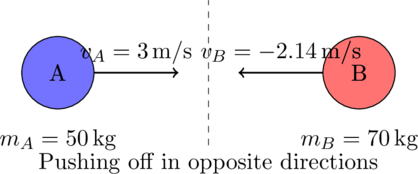
Here’s the detailed Free Body Diagram (FBD) for Question 8: Conservation of Momentum:
We will show skater A and skater B pushing off against each other, representing their masses and velocities. There are no external forces (e.g., friction) acting on the system.
To illustrate the situation after they push off, we represent the directions of their velocities, with Skater A moving to the right and Skater B moving to the left due to the conservation of momentum.
Free Body Diagram (FBD) for Conservation of Momentum:
Explanation:
- Skater A is moving to the right with a velocity of ( v_A = 3 \, \text{m/s} ).
- Skater B is moving to the left with a velocity of ( v_B = -2.14 \, \text{m/s} ) (negative sign indicates opposite direction).
- Both skaters are initially at rest, and after they push off, they move in opposite directions with the system’s total momentum remaining zero.
- Solve for
: From the conservation of momentum equation:
Rearranging to solve for:
Substituting the known values:
Final Answer:
The velocity of skater B is 2.14 m/s in the opposite direction to skater A’s motion.
Try This: 12th Grade Free Body Diagram Physics Question
Rotational Equilibrium on a Beam
A uniform beam of length 4 meters and mass 15 kg is supported at one end by a hinge and at the other by a rope that forms a 30° angle with the beam. What is the tension in the rope if the beam is in rotational equilibrium?
12th Grade Free Body Diagram Physics Question 9
Kinetic Energy and Work
A 1000 kg car accelerates uniformly from rest to a speed of 20 m/s in 10 seconds. How much work is done on the car during this time?
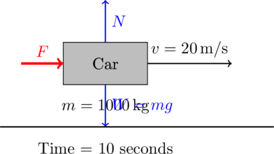
Here is the detailed Free Body Diagram (FBD) for Question 9: Kinetic Energy and Work.
We’ll represent the car, forces acting on it, and how its velocity increases due to the work done by an applied force, leading to a change in kinetic energy.
Since the car is accelerating uniformly, we assume the net force is applied in the horizontal direction, and there are no frictional or air resistance forces.
Free Body Diagram (FBD) for Kinetic Energy and Work
Explanation:
- Car: The rectangular block represents the car with a mass ( m = 1000 \, \text{kg} ).
- Applied Force (( F )): A force is applied to the car, causing it to accelerate uniformly. This force leads to an increase in velocity over 10 seconds.
- Velocity (( v )): After 10 seconds, the car reaches a velocity of ( 20 \, \text{m/s} ).
- Normal Force (( N )): The ground exerts a normal force upward, counteracting the car’s weight.
- Weight (( W )): The car’s weight is ( W = mg = 1000 \times 9.8 \, \text{N} ), acting downward.
This diagram simplifies the understanding of how work is done to accelerate the car, increasing its kinetic energy.
Step-by-Step Solution:
- Determine the work-energy relationship: The work done on the car is equal to the change in its kinetic energy:
Where:
is the mass of the car.
is the final velocity.
is the initial velocity (since the car starts from rest).
- Substitute the values: The initial kinetic energy is zero because the car is initially at rest:
The final kinetic energy is:
Therefore, the work done is:
Final Answer:
The work done on the car is 200,000 J or 200 kJ.
Try this: MCAT Free Body Diagram Physics Question
Forces on a Car Going Around a Curve
A 1000 kg car is moving at a speed of 20 m/s around a curve with a radius of 50 m. If the curve is banked at 10°, what is the minimum coefficient of static friction required to prevent the car from slipping?
12th Grade Free Body Diagram Physics Question
Spring Force (Hooke’s Law)
A spring has a spring constant . How much work is required to stretch the spring 0.5 meters from its natural length?
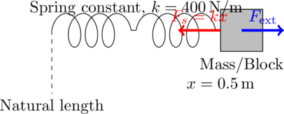
Here’s the detailed Free Body Diagram (FBD) for Question 10: Spring Force (Hooke’s Law), showing the forces acting on the spring as it is stretched.
Free Body Diagram (FBD) using LaTeX:
Explanation of the FBD:
- Spring (Relaxed and Stretched): The spring is shown in its relaxed (natural) state on the left and stretched on the right. The block attached to the end of the spring has displaced it by
.
- Spring Force (
): The spring exerts a restoring force
, which acts to bring the spring back to its natural length. This force is directed towards the left (opposite to the displacement).
- External Force (
): To stretch the spring, an external force
must be applied in the direction of the displacement. This force is directed to the right.
- Spring Constant (
): The stiffness of the spring is given by the spring constant
, which dictates how much force is required to stretch the spring by a certain distance.
This FBD helps visualize the forces involved in stretching the spring and highlights the work done to achieve a displacement of .
Step-by-Step Solution:
- Use Hooke’s Law to calculate the force exerted by the spring: Hooke’s Law states that the force exerted by a spring is proportional to the displacement ( x ) from its natural length:
Where:
is the spring constant.
is the displacement.
- Calculate the work done to stretch the spring: The work done to stretch a spring is given by the formula:
Substituting ( k = 400 \, \text{N/m} ) and ( x = 0.5 \, \text{m} ):
Final Answer:
The work required to stretch the spring 0.5 meters is 50 J.
These questions cover a wide range of free body diagram applications, from basic forces and tensions to more complex systems involving friction, acceleration, and equilibrium.
More on Free Body Diagrams For Advanced Physics Questions
- To understand the basics of free body diagrams, visit the Physics Classroom’s guide on Free Body Diagrams.
- For a deeper dive into the principles behind forces and vectors, check out Khan Academy’s section on Forces and Free Body Diagrams.
- A useful resource for engineering students is MIT’s OpenCourseWare page on Free Body Diagrams.
- You can explore more examples of free body diagrams in various scenarios by visiting HyperPhysics’ page on Free Body Diagrams.
- For a physics tutorial that covers more advanced problems involving free body diagrams, check out the University of Calgary’s Free Body Diagrams resource.
- For advanced physics homework help consider private online or in-home physics tutoring to help master free body diagrams for all questions in 12th grade and beyond!







Leave a Reply